Raspberry Pi: NAS server

I have been wanting to set up my Raspberry Pi as a Network Attached Storage (NAS) drive for quite some time. I eventually got a chance yesterday to give it a go. Unfortunately the Raspberry Pi USB port can’t power my external hard drive and I don’t have a USB hub at the moment, so I just used a 16GB flash drive.
First you need to format your external drive with NTFS. Then place a file on it. Any file will do. I chose a text document so that I can open it and view it on the Pi. Once you have set up your drive, turn off your RasPi, plug the drive into the USB port and then turn on the RasPi. It is safer to plug the USB in when the RasPi is off because some versions don’t have poly fuses on the USB ports.
Once booted up, log in and check to see if the drive is connected.
  • sudo fdisk -l

You can see that my connected drive is right at the bottom. The drive is called sda and because there is only one partition, it is called sda1.
Next you need to create a folder where your drive is going to be mounted into. I called mine myHadrDrive. You also need to give the folder root access so that when you connect to it you are able to read from it and write to it.
  • sudo mkdir /mnt/myHardDrive
  • sudo chmod 0777 myHardDrive
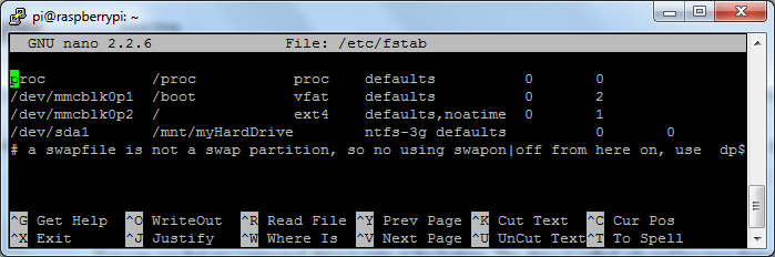
Next you need to mount the hard drive to the folder that has just been created. Open fstab and add the following line to the bottom of the file where it reflects your setup.
  • sudo nano /etc/fstab

Mount the drive
  • sudo mount -a
Now we need to install and set up the Samba server. This will allow a windows machine to connect to the RasPi over the network. Start by installing the following packages using apt-get.
  • sudo apt-get install samba
  • sudo apt-get install samba-common-bin
  • sudo apt-get install ntfs-config
  • sudo apt-get install ntfs-3g
Once all of those packages are installed, edit the Samba configuration file. It took me a while to get this right but with the help of this video, I managed to get it. 
  • sudo nano /etc/samba/smb.conf
Replace the entire file with the following:

#======================= Global Settings =======================
[global]
workgroup = WORKGROUP
server string = raspnas server
netbios name = raspnas
dns proxy = no
### Logging
log file = /var/log/samba/log.%m
max log size = 1000
syslog = 0
panic action = /usr/share/samba/panic-action %d
### Authentication
security = user
map to guest = pi
#======================= Sharered Folders =======================
[media]
path = /mnt/myHardDrive
guest ok = yes
guest account = ftp
browseable = yes
read only = no
create mask = 0777
directory mask = 0777
writeable = yes
admin users = everyone
#==========================================================

A few points to note:
  • WORKGROUP is the workgroup that the drive will be connected to
  • raspnas is the name of he drive on the network
  • path is the folder that you set up earlier
  • Change the file according to your setup
Lastly you need to restart the Samba service and add the user to the Samba database
  • sudo service samba restart
  • sudo smbpasswd -a pi
Now your Samba server is set up. You still need to do one last thing. You need to make sure that the drive gets connected at startup.
  • sudo apt-get install autofs
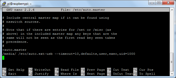
Add the following line to the bottom of the config file
  • sudo nano /etc/auto.master

Reboot your RasPi and then you should be able to log on to the shared drive using your Windows machine.
I hope this has helped anyone who was stuck. If you still have any problems leave a message in the comments and I’ll try help as best I can.
Greg

LabVIEW: Simulating keyboard events

Another useful trick in LabVIEW using the user32.dll is to simulate keys being pressed on the keyboard. I haven’t come across the need very often, however when using console applications, it can be necessary.
I ran into this problem while running a console application that runs a GPS simulator. Getting the application to run was easy and when the simulated trip is complete, the console closes automatically. The problem came in when I wanted to stop the controlling LabVIEW application. When I stopped the LabVIEW application and if the console was still running, I needed to close it and wanted to do it all in one step, instead of forcing the user to stop the LabVIEW application AND close the console window.
After some research I found out that the user32.dll has a keyboard event method so I decided to use that. I first had to make the console window active, find out how here, and then I would run this application as a sub-vi to simulate a Ctrl+C which was needed to stop the GPS simulation and close the console. 

What happens is that the two integers need to be passed to the dll. The first element is the decimal representation of the ASCII character that needs to be simulated and the second is what motion the button makes.
EG: 162 is represents the Ctrl key and 67 is the decimal representation for the ASCII uppercase C. The second integer that is passed to the dll is used to decide what the button is doing. 0 Simulates that the button is being pressed and 2 simulates that the button is being released.
Therefore, by writing each cluster to the dll in a for loop with 50ms delay between loops, Ctrl+C is written to the active console window which will stop the GPS simulation and close the window.
To download the example VI, use this link.
Greg

2W red LED bicycle light update

If you missed the first post about my modified bicycle light, take a look here
So I used my light last weeks at #moonlightmass and it was super cool. I got a few comments about how bright it is and I suppose it’s not a great idea to use this light in a crowd of people. To be seen out on the road by cars, this light is great.

Here is a picture of the modified light mounted on the seat post with the battery pack and controller mounted in a box under the saddle.

Here is a quick video of the light in action.

There are still a few software changes that I need to do like complete the low battery indicator and I also want to add a few more light functions, but that will come when I get a chance.

Greg

Bicycle light using two 1W red LED’s

I bought a 1200 lumen light the other day so that I can cycle before and after work when it is still dark. It works really well to light my way, but I also wanted a decent back light. After all, the cars generally come from behind and need to see you.
Instead of simply buying one, I decided to make one by recycling an old bicycle light that I had lying around and use two 1W red LED’s that I have also had for a while and never used.
The first hurdle I had to overcome was to design a power supply capable of delivering at least 350mA and one that could supply 6.4V, enough for two LED’s. I also wanted to use at the most, two 1.2V NiMH batteries.
The next choice I had to make was what controller I wanted to use. I settled on a small, low cost micro controller. I also decided to run the entire circuit off 5V. This would slightly under drive the LED’s, but would safely power the micro without using two power supplies.
For the power supply, I went with the LM2623 which is capable of supplying 2A with an input of as low as 0.8V.

For the micro controller I went with the PIC12F615 which has an internal nMCLR pull up and an internal 4MHz oscillator which keeps the pin count low.

To drive the 1W LED’s, I am using a BD139 transistor. I am driving it just below its limit, but I had a few lying around so just used one. I am using a PWM signal of 1KHz and the LED’s are on for 50ms and then off for 250ms. At the moment I only have one setting but I plan to add more in my next version, different flash rates and solid on.
I use one of the analog inputs to measure the battery voltage. By doing this I can turn on the 3mm LED when the battery voltage goes below 2V. This means that I won’t run the battery’s too flat and damage them.
The battery’s and controller are housed in a plastic box which I have tied neatly under my saddle and the light is attached to my seat post. 
At the moment this is my prototype which works, but isn’t 100% complete. I still need to tweak the part of the program that measures the battery voltage and I also want to play around with the current limiting resistor so that I can get the max brightness out of the 1W LED’s. I also have to test how long the circuit will run on two AA battery’s.
I will be testing it tonight at Cape Town’s #moonlightmass to see how it performs. I will also get some pictures or videos and put them in a follow-up post. 
If you want the DesignSpark schematic and the micro controller code, use this link.
Greg

LabVIEW: Event Structure vs While Loop

When I started working with Event Structures in LabVIEW, I wondered what the difference was in terms of CPU usage. In a small program, managing efficiency might not be an issue but in a large testing environment where many processes need to be performed, the need for managing efficiency becomes quite important.
To test the difference in CPU usage between using the standard While Loop, which can get messy very quickly and the Event Structure, I wrote a simple program. The While Loop and Event Structure options are placed in different cases which is selected before the program is run. Both options monitor two buttons, display a message when either button is pressed and has a counter which shows how many times the loop is run.
The Event Structure monitors two buttons and displays a message for each. 
The While Loop also monitors two buttons but as it can be seen from the front panel above, it is quite a bit more messy than the Event Structure. If any more button or inputs need to be monitored, this method can quite easily get out of hand.
Here is the CPU monitor comparison of the two options being run. On the left is the Event Structure only using 5% and on the right is the While Loop which is using 30%. There are ways to slow the While Loop down like adding a loop delay but I wanted to show the extremes.
I hope this helps and can provide some display on the different ways to do a similar process.
To download the example VI, use this link.
Greg