Headless Raspberry Pi Setup

Most of my Raspberry Pi’s dotted around the house are set to run headless on WiFi and only accessed over SSH or from a self-hosted webpage. This make running them really easy but setting them up can be tricky. This post is going to cover the basics of getting your headless Raspberry Pi onto a password protected WiFi network without first connecting to it over Ethernet.

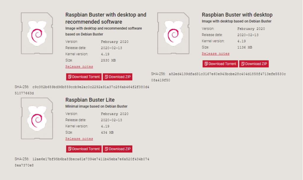
First head over to the Raspberry Pi downloads page and get the latest image. For this post I am using Raspbian Buster Lite.

Once the desired image has been downloaded, flash the image to your SD card. For this I use Etcher however you can also use Win32DiskImager.

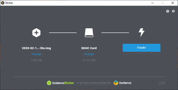
Once the SD card is complete, navigate to the boot partition on the SD card. You may have to remove and replace the SD card into the PC as Etcher normally ejects it when complete.

To configure WiFi and define a network to connect to, create the file wpa_supplicant.conf in the boot partition.

ctrl_interface=DIR=/var/run/wpa_supplicant GROUP=netdev
update_config=1
country=GB
network={
         ssid="some-ssid"
         psk="some-password"
         key_mgmt=WPA-PSK
         id_str="home"
}

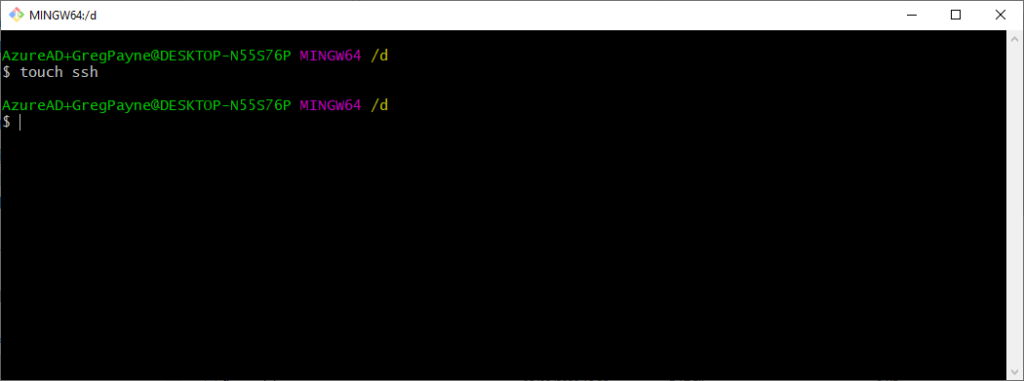
Next you need to enable SSH. By default ssh is turned off. All that needs to be done to get SSH enabled is to create a file called SSH in the boot partition.

touch ssh

This completes the setup off the Raspberry Pi. Insert the SD card into the Raspberry Pi and allow it to boot. If the WiFi setup above is correct, it will connect to the WiFi and get assigned an IP address.

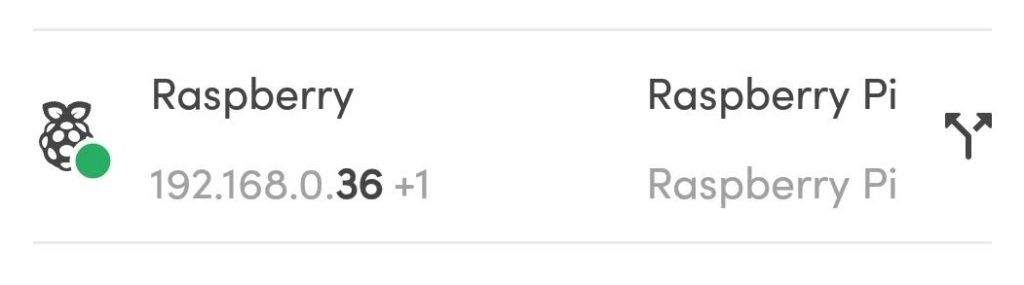
I then use a tool called Fing which will search for all devices on my network. This will give me the assigned IP address of my newly configured Raspberry Pi.

Once you know the IP address you want to connect to, login using SSH and the default password. To set a static IP address, edit dhcpcd.conf.

sudo nano /etc/dhcpcd.conf

And add the following to the bottom of the file. Change the addresses to those that fit your network.

interface wlan0
static ip_address=192.168.0.167/24
static routers=192.168.0.1
static domain_name_servers=192.168.0.1 8.8.8.8

Once you set the static IP address, reboot and connect using the new address.

sudo reboot

Now you can continue with the usual setup:

  • Change the default password
  • Increase the partition size
  • Install applications
    • apt-get: vim, git, python3-pip
    • pip3: flask

Raspberry Pi, Camera and Dropbox

Over the last few months I have been preparing my project and presentation for the UK CLD Summit. Now that the CLD Summit is over, I wanted to do a quick and fun project on my Raspberry Pi that has been lying in a box for those few months.

Something that I have wanted to do for a while is get a webcam working and be able to take pictures. I don’t have the Raspberry Pi camera, so just used a normal webcam. I used the Logitech C170 connected directly to the USB port of my Raspberry Pi and it worked really well. The other USB port has a WiFi dongle connected.

Raspberry Pi Camera Dropbox

I have this connected up and looking out my window so please excuse the lack of quality.

So to get started, make sure your Raspberry Pi has been updated. I have used the standard Rasbian image.

apt-get update
apt-get upgrade
rpi-update

Setting up a webcam:

Then you need to install fswebcam

apt-get install fswebcam

Once all the above has been installed, plug your webcam in and reboot. Make sure that your webcam is seen by the system.

lsusb
Bus 001 Device 005: ID 046d:082b Logitech, Inc.

There are many switches and options available, so I will explain what I used and how to get a full list. Run this command to capture an image.

fswebcam -r 640x480 -S 10 -d /dev/video0 webcam.png

fswebcam

  • The program that is being executed

-r 640x480

  • Setting the resolution for the image

-S 10

  • Skip the first 10 captures. With my webcam, if I save the first image captured, it gets corrupted. So by adding this option, the camera takes 10 images and only saves the last one.

-d /dev/video

  • This sets the device name. To get yours, execute ls /dev/ and look to see what your device is called

webcam.png

  • This is the file name of the saved image

By executing fsweb -h, you can see all the options.

You will now have the image saved to the location of your choice. If you are running headless like I do, you have no idea if the image is correct. You could FTP into your Raspberry Pi and get the image off, or like I have done, link my Raspberry Pi to my Dropbox account.

Linking a Dropbox account:

 It took me a few attempts to get my Raspberry Pi and Dropbox account linked, but got there in the end.

First you need to download the Dropbox_Uploader script from git. I then copied the script file to the folder where I am saving my pictures to. You don’t have to do this, however it saves writing full paths when executing the commands.

Once the script is in the location you want it, you need to make it executable.

chmod +x dropbox_uploader.sh

Make sure you have a Dropbox account before executing the script. Once you have an account, then you are ready to start linking the two. Run the script and follow the prompts.

./dropbox_uploader.sh

The settings that I used when setting up my App were:

  • Files and Datastore
  • No – My app needs access to files already on Dropbox
  • All file types – My app needs access to a user’s full Dropbox
  • Add a unique name, you might need to try a few

Verify your app and if successful, you will notice a folder called Apps has now been created in your Dropbox account. I had to wait a few minutes for this to update.

Test if your account has been linked properly by getting a list of folders in your account.

./dropbox_uploader.sh list

If this works, you are ready to start uploading your images.

./dropbox_uploader.sh upload image.png /Apps/App_Name/File_Name

Wait a few seconds and the image should appear at the location you uploaded it to. Now you can see if the image you captured in the previous steps has worked.

Here is a time lapse video that I put together using Windows Movie Maker. I set up a cron job and ran a script every minute.

If you have any questions, please leave them below in the comments and I’ll try help where I can.

Greg

LabVIEW and Raspberry Pi TCP/IP Communications

A few months ago I did the LabVIEW Connectivity course at National Instruments UK. I really enjoyed it but haven’t got around to trying any of the concepts out yet. Last week I decided to write a TCP/IP chat program working between LabVIEW running on my Windows laptop and Python running my Raspberry Pi.
On the left of the you can see the LabVEIW front panel running the server. On the right is the putty terminal running a Python client. At the moment I only have the functionality to connect one client to the server.
This little project got me thinking and I learnt quite a few new concepts.
LabVIEW Server:
I used the LabVIEW example finder to get started.
The LabVIEW server starts off my listening for connections. I have set a 60 sec timeout for this wait. Once connected, there are two parallel loops running. One loop is used to transmit strings and the other loop is used to receive strings.
To transmit a string, the user types the string in the User Input control and presses the Return key. An end of line character is then concatenated onto the string which is transmitted using TCP Write.
To receive a string, the TCP Read function listens with a timeout of 100 ms. If a string is received, it is concatenated onto the Response String indicator.
Python Client:
This is where things got interesting. I needed to use threads, timeouts and sockets, each of which I have never used before. This client was written in Python 3.2.

I ended up using two threads. One for the transmit and the other for the receive controls.

I used a global variable which is used to stop the threads when the client or server is stopped. I also needed to use a timeout in both the transmit and receive thread because the recv() and readline() methods blocked the program flow which locked up the threads if the client was stopped.

With the timeout set, I could monitor the global variable and return cleanly from the thread when the client or server was stopped.

First start the LabVIEW server, then within 60 sec run the Python client. The connection will be established and you will be able to send strings between LabVIEW and the Raspberry Pi. To stop the programs, either use the Stop button in LabVIEW or CTRL+C in Python. Both methods will stop both the server and the client.

I am sure there are many methods to do what I have done here, even better, cleaner ones. My Python is all self taught and only being used for my hobbies. I am using my Raspberry Pi for what is was designed for; learning. If you can recommend a better way to do this, please let me know because I am always keen to learn something new.

Greg

Raspberry Pi: 3x3x3 LED Cube

If you do a web search for LED cubes, you will notice that they have been built so many times and anything less than 8x8x8 is a bit of a waste of time. Knowing all of this, and basically because I am bored out of my mind, I decided to go ahead and build one with old parts lying around at home. 
I ended up with a small 3x3x3 LED cube connected to my Raspberry Pi. I chose 3x3x3 because no extra hardware is needed. All I needed to do was find 27 LED’s which I took off an old LED matrix sign board. 
The basic concept is this; the cube, in this case 3x3x3, is made up of columns (9) and layers (3).On each layer, all the cathodes are connected together and in each column, the anodes are connected together. Therefore, 12 ouputs are needed to control all 27 LED’s.
By driving the layer output low and the column output high, the specific LED will turn on. Driving both the layer and column output low, will turn the LED off. By sequencing what LED is on when, you can draw different patterns. The bigger the cube, the better patterns can be drawn.

Update:
I have drawn up a schematic to show the hardware connections for the cube and the cube to he RasPi’s GPIO header.

You can download a schematic here.

Take a look at this 32x32x32 LED cube that someone build.
I wrote my code in Python3.2 using the Rpi.GPIO library.

Greg

Raspberry Pi: MCP23008 Port Expander

I have been wanting to get an MCP23008 I2C port expander connected to my Raspberry Pi for quite a while. I finally got one and during my breaks from LabVIEW CLD exam preparation, made the circuit on some strip board. 

Using the Quick2Wire Python I2C library makes getting this working really quick and easy. Just make sure you place your LED’s the correct way around. I spent a bit of time debugging the I2C until I thought of checking the obvious. 
Currently I only have the outputs working as I didn’t have any switches with me. I’ll add two switches and get that going next. 
Here is the code that I used. I set up a little menu to select which LED to turn on or off. 
Next I plan to get the software PWM working so that I can connect up to Cheerlights. Need to do some more studying and then will get that going. Also need some RGB LED’s first.
Until next time, happy coding.
Greg